
Lab 3 : Implementing Spanning Tree
This lab demonstrates basic configuration and monitoring tasks when implementing spanning tree and some related protection features on EX Series Ethernet Switches. In this lab, you will use the command-line interface (CLI) to configure and monitor RSTP as well as bridge protocol data unit (BPDU) and loop protection.
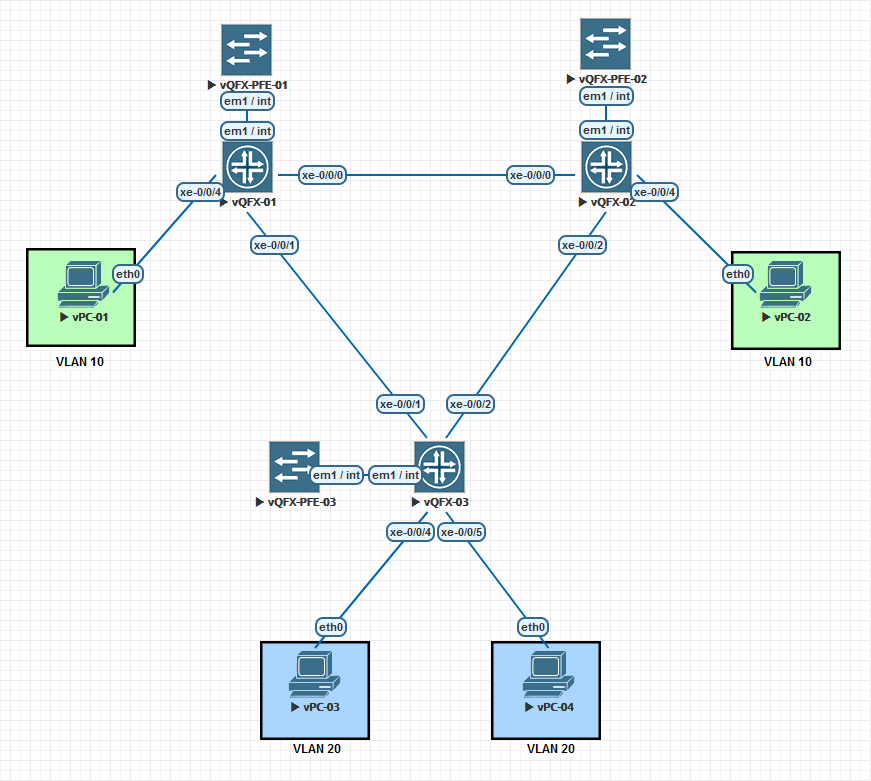
EVE-NG Network Topology
You can either modify the existing lab topology that you created from Lab 2, or you can clone that topology to a new one and name it Lab 3. If you clone the topology, you will need to implement everything from Lab1 and Lab2 into the new lab topology to follow this guide as we will be modifying this lab as if we are continuing from the previous lab configurations.
Below is an export from Lab2 configurations.
set system host-name vqfx-01
set system root-authentication encrypted-password "$1$KrovnU1S$AHV6IRreiZIuP4RA526TH0"
set system services ssh root-login allow
set system services netconf ssh
set system services rest http port 8080
set system services rest enable-explorer
set system syslog user * any emergency
set system syslog file messages any notice
set system syslog file messages authorization info
set system syslog file interactive-commands interactive-commands any
set interfaces xe-0/0/0 description "Switch Trunk Interface"
set interfaces xe-0/0/0 unit 0 family ethernet-switching interface-mode trunk
set interfaces xe-0/0/0 unit 0 family ethernet-switching vlan members 10
set interfaces xe-0/0/0 unit 0 family ethernet-switching vlan members 20
set interfaces xe-0/0/1 description "vPC VLAN 10"
set interfaces xe-0/0/1 unit 0 family ethernet-switching interface-mode access
set interfaces xe-0/0/1 unit 0 family ethernet-switching vlan members 10
set interfaces xe-0/0/2 description "vPC VLAN 20"
set interfaces xe-0/0/2 unit 0 family ethernet-switching interface-mode access
set interfaces xe-0/0/2 unit 0 family ethernet-switching vlan members 20
set interfaces em0 unit 0 family inet dhcp
set interfaces em1 unit 0 family inet address 169.254.0.2/24
set interfaces irb unit 10 family inet address 10.0.10.1/24
set interfaces irb unit 20 family inet address 10.0.20.1/24
set forwarding-options storm-control-profiles default all
set protocols igmp-snooping vlan default
set vlans VLAN-10 vlan-id 10
set vlans VLAN-10 l3-interface irb.10
set vlans VLAN-20 vlan-id 20
set vlans VLAN-20 l3-interface irb.20
set vlans default vlan-id 1

----------

set system host-name vqfx-02
set system root-authentication encrypted-password "$1$Kfz7PEKs$lUYDMK/olBURdugO4BTmX0"
set system services ssh root-login allow
set system services netconf ssh
set system services rest http port 8080
set system services rest enable-explorer
set system syslog user * any emergency
set system syslog file messages any notice
set system syslog file messages authorization info
set system syslog file interactive-commands interactive-commands any
set interfaces xe-0/0/0 description "Switch Trunk Interface"
set interfaces xe-0/0/0 unit 0 family ethernet-switching interface-mode trunk
set interfaces xe-0/0/0 unit 0 family ethernet-switching vlan members 10
set interfaces xe-0/0/0 unit 0 family ethernet-switching vlan members 20
set interfaces xe-0/0/1 description "vPC VLAN 10"
set interfaces xe-0/0/1 unit 0 family ethernet-switching interface-mode access
set interfaces xe-0/0/1 unit 0 family ethernet-switching vlan members 10
set interfaces xe-0/0/2 description "vPC VLAN 20"
set interfaces xe-0/0/2 unit 0 family ethernet-switching interface-mode access
set interfaces xe-0/0/2 unit 0 family ethernet-switching vlan members 20
set interfaces em0 unit 0 family inet dhcp
set interfaces em1 unit 0 family inet address 169.254.0.2/24
set forwarding-options storm-control-profiles default all
set protocols igmp-snooping vlan default
set vlans VLAN-10 vlan-id 10
set vlans VLAN-20 vlan-id 20
set vlans default vlan-id 1
Modify the Existing Configuration
In Lab 3, we have expanded the switched network to now include three (3) vQFX switches and moved some of the link connections around for the switch to switch links and the vPC links. Having three switches will allow us to easily create a realistic network “loop” that happens frequently in real world scenarios.
First, you will need to clear the interface configurations for the old vPC links. Run the following commands on vQFX-01 and vQFX-02. vQFX-01 will remain the Layer 3 VLAN router at this time.
delete interfaces xe-0/0/1
delete interfaces xe-0/0/2
Now we need to move our vPC connections to their new interfaces. Execute the following commands on vQFX-01 and vQFX-02.
set interfaces xe-0/0/4 description "vPC VLAN 10"
set interfaces xe-0/0/4 unit 0 family ethernet-switching interface-mode access
set interfaces xe-0/0/4 unit 0 family ethernet-switching vlan members 10

commit
Since we have also added a new vQFX switch to the network, we will need to get this switch ready to add into the network. First, lets clean up the configurations from the evaluation configs.
delete system root-authentication
delete system login
delete system extensions

wildcard delete interfaces xe-*
wildcard delete interfaces et-*

set system root-authentication plain-text-password

commit
Now we are going to confirm that we have everything reconfigured correctly. vPC-01 should be able to communicate with vPC-02, but should not be able to communicate with vPC-03 and vPC-04.
vPC-01> ping 10.0.10.12

84 bytes from 10.0.10.12 icmp_seq=1 ttl=64 time=14.914 ms
84 bytes from 10.0.10.12 icmp_seq=2 ttl=64 time=15.786 ms
84 bytes from 10.0.10.12 icmp_seq=3 ttl=64 time=16.276 ms
84 bytes from 10.0.10.12 icmp_seq=4 ttl=64 time=15.813 ms
84 bytes from 10.0.10.12 icmp_seq=5 ttl=64 time=15.986 ms


vPC-01> ping 10.0.20.11

10.0.20.11 icmp_seq=1 timeout
10.0.20.11 icmp_seq=2 timeout
10.0.20.11 icmp_seq=3 timeout
10.0.20.11 icmp_seq=4 timeout
10.0.20.11 icmp_seq=5 timeout


vPC-01> ping 10.0.20.12

10.0.20.12 icmp_seq=1 timeout
10.0.20.12 icmp_seq=2 timeout
10.0.20.12 icmp_seq=3 timeout
10.0.20.12 icmp_seq=4 timeout
10.0.20.12 icmp_seq=5 timeout
We are now ready to start integrating the new switch into the network topology.
Configuring and Monitoring RSTP
We are first going to configure the RSTP protocols on the vQFX-01 and vQFX-02 switches. vQFX-01 is going to be set as the root bridge and vQFX-02 is going to be configured as the secondary root bridge for the network. The root bridge is configured by setting the bridge priority value on each switch. In most cases, you will only set the primary and secondary bridge priorities, and all additional switches will be left with their default value of 32K.
On vQFX-01, we are going to set the bridge priority to 4K, thereby forcing it to be the primary root bridge as it has the lowest priority. With Spanning Tree, the lower the priority, the more referred it becomes. Run the following commands on vQFX-01.
set protocols rstp bridge-priority 4k
set protocols rstp interface all
On vQFX-02, we are going to set the bridge priority to 8K, thereby forcing it to be the secondary root bridge as it has the lower priority from default of 32K. With Spanning Tree, the lower the priority, the more referred it becomes. Run the following commands on vQFX-02.
set protocols rstp bridge-priority 8k
set protocols rstp interface all
We have also set the RSTP protocol to include all interfaces by default in the Spanning Tree services. This means that all interfaces, by default, will listen and transmit BPDU packets.
Lets confirm that spanning tree is working correctly now. From vQFX-02, run the command run show spanning-tree bridge. You should see the ROOT priority value of 4096 with a root port of xe-0/0/0 and the local bridge priority of 8192.
root@vqfx-02# run show spanning-tree bridge
STP bridge parameters
Routing instance name : GLOBAL
Context ID : 0
Enabled protocol : RSTP
Root ID : 4096.02:05:86:71:0c:02
Root cost : 2000
Root port : xe-0/0/0
Hello time : 2 seconds
Maximum age : 20 seconds
Forward delay : 15 seconds
Message age : 1
Number of topology changes : 1
Time since last topology change : 342 seconds
Local parameters
Bridge ID : 8192.02:05:86:71:cc:02
Extended system ID : 0
Now from vQFX-01, run the command run show spanning-tree interface. You should see all interfaces with a forwarding state and as a designated port role.
root@vqfx-01# run show spanning-tree interface

Spanning tree interface parameters for instance 0

Interface                  Port ID    Designated         Designated         Port    State  Role
                                       port ID           bridge ID          Cost
xe-0/0/0                   128:490      128:490   4096.020586710c02         2000    FWD    DESG
xe-0/0/4                   128:491      128:491   4096.020586710c02         2000    FWD    DESG
If you run the command run show spanning-tree bridge on the vQFX-01 switch, you can see that the local switch is also acting as the primary ROOT bridge.
root@vqfx-01# run show spanning-tree bridge
STP bridge parameters
Routing instance name               : GLOBAL
Context ID                          : 0
Enabled protocol                    : RSTP
  Root ID                           : 4096.02:05:86:71:0c:02
  Hello time                        : 2 seconds
  Maximum age                       : 20 seconds
  Forward delay                     : 15 seconds
  Message age                       : 0
  Number of topology changes        : 1
  Time since last topology change   : 814 seconds
  Local parameters
    Bridge ID                       : 4096.02:05:86:71:0c:02
    Extended system ID              : 0
Now we are going to configure our interfaces that link to the new switch. These interfaces will be configured as TRUNK ports, identical to xe-0/0/0 with VLAN 10 and VLAN 20 transporting via the interfaces.
On vQFX-01, apply the following configuration to enable interface xe-0/0/1 connecting to vQFX-03
set interfaces xe-0/0/1 description "Switch vQFX-03 Trunk Interface"
set interfaces xe-0/0/1 unit 0 family ethernet-switching interface-mode trunk
set interfaces xe-0/0/1 unit 0 family ethernet-switching vlan members 10
set interfaces xe-0/0/1 unit 0 family ethernet-switching vlan members 20

commit
And then on vQFX-02, apply the following configuration to enable interface xe-0/0/2 connecting to vQFX-03
set interfaces xe-0/0/2 description "Switch vQFX-03 Trunk Interface"
set interfaces xe-0/0/2 unit 0 family ethernet-switching interface-mode trunk
set interfaces xe-0/0/2 unit 0 family ethernet-switching vlan members 10
set interfaces xe-0/0/2 unit 0 family ethernet-switching vlan members 20

commit
We are now ready to bring vQFX-03 into the network connectivity. Apply the following configurations to vQFX-03 to activate interfaces xe-0/0/1 and xe-0/0/2 along with the RSTP protocol.
We are also going to configure the VLANs on this switch and allocate the interfaces for the vPC connections.
set interfaces xe-0/0/1 description "Switch vQFX-01 Trunk Interface"
set interfaces xe-0/0/1 unit 0 family ethernet-switching interface-mode trunk
set interfaces xe-0/0/1 unit 0 family ethernet-switching vlan members 10
set interfaces xe-0/0/1 unit 0 family ethernet-switching vlan members 20

set interfaces xe-0/0/2 description "Switch vQFX-02 Trunk Interface"
set interfaces xe-0/0/2 unit 0 family ethernet-switching interface-mode trunk
set interfaces xe-0/0/2 unit 0 family ethernet-switching vlan members 10
set interfaces xe-0/0/2 unit 0 family ethernet-switching vlan members 20

set interfaces xe-0/0/4 description "vPC VLAN 20"
set interfaces xe-0/0/4 unit 0 family ethernet-switching interface-mode access
set interfaces xe-0/0/4 unit 0 family ethernet-switching vlan members 20

set interfaces xe-0/0/5 description "vPC VLAN 20"
set interfaces xe-0/0/5 unit 0 family ethernet-switching interface-mode access
set interfaces xe-0/0/5 unit 0 family ethernet-switching vlan members 20

set protocols rstp interface all

set vlans VLAN-10 vlan-id 10
set vlans VLAN-20 vlan-id 20

commit
Now lets see if vPC-01 can communicate with vPC-03 and vPC-04 again ?
vPC-01> ping 10.0.20.11

10.0.20.11 icmp_seq=1 timeout
84 bytes from 10.0.20.11 icmp_seq=2 ttl=63 time=17.233 ms
84 bytes from 10.0.20.11 icmp_seq=3 ttl=63 time=16.662 ms
84 bytes from 10.0.20.11 icmp_seq=4 ttl=63 time=17.136 ms
84 bytes from 10.0.20.11 icmp_seq=5 ttl=63 time=17.962 ms

vPC-01> ping 10.0.20.12

10.0.20.12 icmp_seq=1 timeout
84 bytes from 10.0.20.12 icmp_seq=2 ttl=63 time=19.611 ms
84 bytes from 10.0.20.12 icmp_seq=3 ttl=63 time=18.233 ms
84 bytes from 10.0.20.12 icmp_seq=4 ttl=63 time=24.377 ms
84 bytes from 10.0.20.12 icmp_seq=5 ttl=63 time=16.359 ms
Good. The vPC machines can communicate again. Now, lets look at the spanning tree instance on vQFX-03. Run the command run show spanning-tree interface on the vQFX-03 switch. Why is there not a loop in the network ?
root@vqfx-03# run show spanning-tree interface

Spanning tree interface parameters for instance 0

Interface                  Port ID    Designated         Designated         Port    State  Role
                                       port ID           bridge ID          Cost
xe-0/0/1                   128:490      128:496   4096.020586710c02         2000    FWD    ROOT
xe-0/0/2                   128:491      128:495   8192.02058671cc02         2000    BLK    ALT
xe-0/0/4                   128:495      128:495  32768.020586714702         2000    FWD    DESG
xe-0/0/5                   128:496      128:496  32768.020586714702         2000    FWD    DESG
What interface is the ROOT interface, what interface is being blocked and why is it being blocked ?
The ROOT interface is xe-0/0/1 because that is the closest path to the lowest bridge priority (primary). The secondary path xe-0/0/2 is being blocked because the bridge priority is higher. This his how RSTP protects again a loop that was created in the network.
Configuring and Monitoring BPDU Protection
We are now going to enable some spanning tree BPDU protection features. First, we are going to configure interface xe-0/0/1 on vQFX-03 as an edge port and then configure spanning tree to block BPDU packets on all edge ports.
set protocols rstp bpdu-block-on-edge
set protocols rstp interface xe-0/0/1 edge

commit
Now look at your spanning tree topology. What did interface xe-0/0/1 do ?
root@vqfx-03# run show spanning-tree interface

Spanning tree interface parameters for instance 0

Interface                  Port ID    Designated         Designated         Port    State  Role
                                       port ID           bridge ID          Cost
xe-0/0/1                   128:490      128:490  32768.020586714702         2000    FWD    DESG
xe-0/0/2                   128:491      128:495   8192.02058671cc02         2000    FWD    ROOT
xe-0/0/4                   128:495      128:495  32768.020586714702         2000    FWD    DESG
xe-0/0/5                   128:496      128:496  32768.020586714702         2000    FWD    DESG
Why is interface xe-0/0/1 no longer seen as the root bridge?
Why is interface xe-0/0/2 now the root port ?
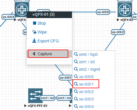
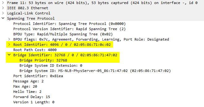
Interface xe-0/0/1 is no longer accepting any BPDU packets on that interface because we forced it to be an edge mode port. The command rstp bpdu-block-on-edge forced any port configured as an Edge port to block all BPDU packets. BPDU packets are still being sent out however. This can be seen if you run a packet capture on the vQFX-01 switch interface xe-0/0/1.
What switch is now performing the loop protection and blocking ?
If you look at vQFX-01, you will now see interface xe-0/0/1 is in a blocking state, even though it is the root switch. While the port is still in DESG mode, it has to protect against a loop.
root@vqfx-01# run show spanning-tree interface

Spanning tree interface parameters for instance 0

Interface                  Port ID    Designated         Designated         Port    State  Role
                                       port ID           bridge ID          Cost
xe-0/0/0                   128:490      128:490   4096.020586710c02         2000    FWD    DESG
xe-0/0/4                   128:491      128:491   4096.020586710c02         2000    FWD    DESG
xe-0/0/1                   128:496      128:496   4096.020586710c02         2000    BLK    DESG