
Lab 2 : Implementing Virtual Networks
This lab demonstrates basic configuration and monitoring tasks when implementing virtual networks on EX/QFX series switches. In this lab, we will be using EVE-NG as our emulation platform running two (2) vQFX v15.1X53-D60 virtual switches.
You will use the command-line interface (CLI) to configure and monitor VLANs and inter-VLAN routing operations.
EVE-NG Lab Topology
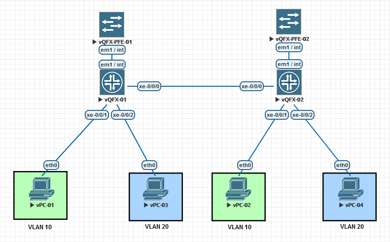
You can either modify the existing lab topology that you created from Lab 1, or you can clone that topology to a new one and name it Lab 2. If you clone the topology, you will need to implement everything from Lab1 into the new lab topology to follow this guide as we will be modifying this lab as if we are continuing from the previous lab configurations.
Continuing from the Lab1 topology, you will need to add two (2) additional vPC VMs, one per switch, and connect them to the interface xe-0/0/2 on each switch. Once connected, we will reconfigure each of the RE appliances.
vPC IP Address Assignments
| Hostname | VLAN Assignment |
IPv4 Address | Gateway |
| vPC-01 | 10 | 10.0.10.11/24 | 10.0.10.1 |
| vPC-02 | 10 | 10.0.10.12/24 | 10.0.10.1 |
| vPC-03 | 20 | 10.0.20.11/24 | 10.0.20.1 |
| vPC-04 | 20 | 10.0.20.12/24 | 10.0.20.1 |
Using the table above, configure each of the vPC devices with the hostname and IPv4 address.
set pcname {{hostname}}
ip {{ip-address-cidr}} {{gateway}}
Modifying Existing Configurations
We are now going to log into each of the RE appliances and remove the configurations that we previously setup. We are going to remove the interface range configurations from Lab1, and setup each interface independently.
delete interfaces interface-range L2_VLAN1
wildcard delete interfaces xe-*
Configuring and Monitoring Virtual Networks
Now all of our previous interface configurations have been removed, and we are ready to reconfigure our switches to support multi-VLAN trunking and inter-VLAN routing.
Next, we are going to configure both RE appliances with the VLANs 10 and 20. Enter the following configurations on each RE appliance.
set vlans VLAN-10 vlan-id 10
set vlans VLAN-20 vlan-id 20
Now we are going to configure the vPC uplink interfaces to their assigned VLAN. Enter the following configurations on each RE appliance.
set interfaces xe-0/0/1 description "vPC VLAN 10"
set interfaces xe-0/0/1 unit 0 family ethernet-switching interface-mode access
set interfaces xe-0/0/1 unit 0 family ethernet-switching vlan members 10

set interfaces xe-0/0/1 description "vPC VLAN 20"
set interfaces xe-0/0/2 unit 0 family ethernet-switching interface-mode access
set interfaces xe-0/0/2 unit 0 family ethernet-switching vlan members 20
We now need to configure the TRUNK interface between the two switches so that the tagged VLANs can communicate between the switches. We are going to configure interface xe-0/0/0 as the trunk on each switch. Enter the following configuration on each RE.
set interfaces xe-0/0/0 description "Switch Trunk Interface"
set interfaces xe-0/0/0 unit 0 family ethernet-switching interface-mode trunk
set interfaces xe-0/0/0 unit 0 family ethernet-switching vlan members 10
set interfaces xe-0/0/0 unit 0 family ethernet-switching vlan members 20

commit
Now lets take a look at the VLANs that are configured on the switch. Run the following command to view the VLANs configured and running.
run show vlans
How many VLANs are listed now? How many of those VLANs are tagged VLANs?
root@vqfx-re# run show vlans

Routing instance        VLAN name             Tag          Interfaces
default-switch          VLAN-10               10
                                                           xe-0/0/0.0*
                                                           xe-0/0/1.0*
default-switch          VLAN-20               20
                                                           xe-0/0/0.0*
                                                           xe-0/0/2.0*
default-switch          default               1
Why is interface xe-0/0/0 listed in both VLAN 10 and VLAN 20 ?
You can also append the command detail or extensive to the show vlans command.
root@vqfx-re# run show vlans detail

Routing instance: default-switch
  VLAN Name: VLAN-10                        State: Active
Tag: 10
Internal index: 3, Generation Index: 3, Origin: Static
MAC aging time: 300 seconds
VXLAN Enabled : No
Interfaces:
    xe-0/0/0.0*,tagged,trunk
    xe-0/0/1.0*,untagged,access
Number of interfaces: Tagged 1    , Untagged 1
Total MAC count: 2

Routing instance: default-switch
  VLAN Name: VLAN-20                        State: Active
Tag: 20
Internal index: 4, Generation Index: 4, Origin: Static
MAC aging time: 300 seconds
VXLAN Enabled : No
Interfaces:
    xe-0/0/0.0*,tagged,trunk
    xe-0/0/2.0*,untagged,access
Number of interfaces: Tagged 1    , Untagged 1
Total MAC count: 2

Routing instance: default-switch
  VLAN Name: default                        State: Active
Tag: 1
Internal index: 2, Generation Index: 2, Origin: Static
MAC aging time: 300 seconds
VXLAN Enabled : No
Number of interfaces: Tagged 0    , Untagged 0
Total MAC count: 0
Now test if the vPC VMs can communicate with each other. From vPC-01, try to ping vPC-02 — does it respond? Next, from vPC-01, try to ping vPC-03 or vPC-04? Do they respond?
vPC-01> ping 10.0.10.12

84 bytes from 10.0.10.12 icmp_seq=1 ttl=64 time=15.756 ms
84 bytes from 10.0.10.12 icmp_seq=2 ttl=64 time=19.032 ms
84 bytes from 10.0.10.12 icmp_seq=3 ttl=64 time=17.012 ms
84 bytes from 10.0.10.12 icmp_seq=4 ttl=64 time=16.167 ms
84 bytes from 10.0.10.12 icmp_seq=5 ttl=64 time=17.100 ms

----------

vPC-01> ping 10.0.20.11

host (10.0.10.1) not reachable

----------

vPC-01> ping 10.0.20.12

host (10.0.10.1) not reachable
vPC-01 and vPC-02 can communicate with each other because they are on the same VLAN (VLAN 10) and because their IPv4 subnet is the same.
vPC-01 and vPC-02 can not communicate with vPC-03 or vPC-04 because they are on different VLANs (VLAN 10 vs VLAN 20) and because they are on different IPv4 subnets. Even if they were within the same subnet, they would not be able to communicate with each other due to the separation of the VLANs.
Configuring and Monitoring Inter-VLAN Routing
We are now going to configure Inter-VLAN routing. Inter-VLAN routing will allow the devices on each of the two VLANs be able to communicate with each other, by “routing” the packages at Layer 3.
On vQFX-01, enter the following commands to configure the Layer 3 routing interfaces for each VLAN.
set interfaces irb unit 10 family inet address 10.0.10.1/24
set interfaces irb unit 20 family inet address 10.0.20.1/24
Next, we are going to tell the VLANs what Layer 3 interface is responsible for performing the routing. For now, you only need to configure these settings on vQFX-01. vQFX-02 will remain a Layer 2 device only and will not perform routing.
set vlans VLAN-10 l3-interface irb.10
set vlans VLAN-20 l3-interface irb.20

commit
Lets test again from vPC-01 to see if we can communicate with vPC-03 and vPC-04.
vPC-01> ping 10.0.20.11

10.0.20.11 icmp_seq=1 timeout
84 bytes from 10.0.20.11 icmp_seq=2 ttl=63 time=10.092 ms
84 bytes from 10.0.20.11 icmp_seq=3 ttl=63 time=8.982 ms
84 bytes from 10.0.20.11 icmp_seq=4 ttl=63 time=8.424 ms
84 bytes from 10.0.20.11 icmp_seq=5 ttl=63 time=12.491 ms
You will notice that the first packet times out. Why ?
The first packet timeout is caused because the host vPC-01 has to perform an ARP request. After the ARP packet is returned, the host can then successfully complete the connection via Inter-VLAN routing.
From vQFX-01, if you show the ARP table, you will see the ARP table entries in the switch, and what interface the packets will transport via.
root@vqfx-re# run show arp | match irb

00:50:79:66:68:06 10.0.10.11      10.0.10.11                irb.10 [xe-0/0/1.0]     none
00:50:79:66:68:05 10.0.10.12      10.0.10.12                irb.10 [xe-0/0/0.0]     none
00:50:79:66:68:07 10.0.20.11      10.0.20.11                irb.20 [xe-0/0/2.0]     none
00:50:79:66:68:08 10.0.20.12      10.0.20.12                irb.20 [xe-0/0/0.0]     none
Now lets look at the routing table on the switch. Execute the command run show route on vQFX-01 to see the switches Layer 3 routing table.
root@vqfx-re# run show route

inet.0: 6 destinations, 6 routes (6 active, 0 holddown, 0 hidden)
+ = Active Route, - = Last Active, * = Both

10.0.10.0/24       *[Direct/0] 00:08:34
                    > via irb.10
10.0.10.1/32       *[Local/0] 00:08:34
                      Local via irb.10
10.0.20.0/24       *[Direct/0] 00:08:34
                    > via irb.20
10.0.20.1/32       *[Local/0] 00:08:34
                      Local via irb.20