
Lab 1 : Implementing Layer 2 Switching
This lab demonstrates basic configuration and monitoring tasks when implementing Layer 2 switching on EX/QFX series switches. In this lab, we will be using EVE-NG as our emulation platform running two (2) vQFX v15.1X53-D60 virtual switches.
You will use the command-line interface (CLI) to configure and monitor Layer 2 interfaces and basic bridging operations.
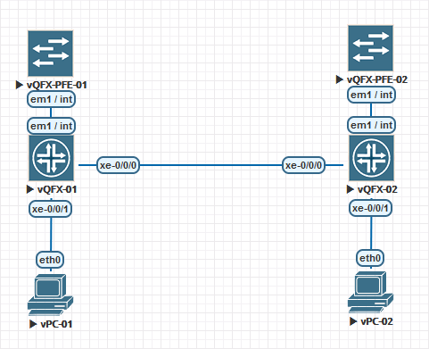
EVE-NG Lab Topology
vQFX switches in EVE-NG are setup with the PFE and the RE as two separate appliances.
Boot-up of the appliances can take up to 15 minutes depending on your EVE-NG server setup.
First, we need to login to each Routing Engine (RE) to access the CLI.
Default Username: root
Default Password: Juniper
Once you are logged in, you will want to remove some default configurations to clean up the evaluation configurations that are present.
delete system root-authentication
delete system login
delete system extensions

wildcard delete interfaces xe-*
wildcard delete interfaces et-*
To reset the root user account password, enter the following command.
set system root-authentication plain-text-password
Your base configuration on both RE VMs should now look like the following:
{master:0}[edit]
root@vqfx-re# show

version 15.1X53-D60.4;
system {
    host-name vqfx-re;
    root-authentication {
        encrypted-password "$1$/P210/sD$oCMnLwyfean4XFVgw7WyP."; ## SECRET-DATA
    }
    services {
        ssh {
            root-login allow;
        }
        netconf {
            ssh;
        }
        rest {
            http {
                port 8080;
            }
            enable-explorer;
        }
    }
    syslog {
        user * {
            any emergency;
        }
        file messages {
            any notice;
            authorization info;
        }
        file interactive-commands {
            interactive-commands any;
        }
    }
}
interfaces {
    em0 {
        unit 0 {
            family inet {
                dhcp;
            }
        }
    }
    em1 {
        unit 0 {
            family inet {
                address 169.254.0.2/24;
            }
        }
    }
}
forwarding-options {
    storm-control-profiles default {
        all;
    }
}
protocols {
    igmp-snooping {
        vlan default;
    }
}
vlans {
    default {
        vlan-id 1;
    }
}
{master:0}[edit]
root@vqfx-re# show | display set

set version 15.1X53-D60.4
set system host-name vqfx-re
set system root-authentication encrypted-password "$1$/P210/sD$oCMnLwyfean4XFVgw7WyP."
set system services ssh root-login allow
set system services netconf ssh
set system services rest http port 8080
set system services rest enable-explorer
set system syslog user * any emergency
set system syslog file messages any notice
set system syslog file messages authorization info
set system syslog file interactive-commands interactive-commands any
set interfaces em0 unit 0 family inet dhcp
set interfaces em1 unit 0 family inet address 169.254.0.2/24
set forwarding-options storm-control-profiles default all
set protocols igmp-snooping vlan default
set vlans default vlan-id 1
Configure Layer2 Interfaces
We are now ready to configure the interfaces linking the devices to each other. Interface “xe-0/0/0” is the link between the two switches, and interface “xe-0/0/1” is the link connecting the two virtual PCs. Enter the following commands to configure the interfaces on each RE:
set interfaces xe-0/0/0 description "Switch to Switch Link"
set interfaces xe-0/0/0 unit 0 family ethernet-switching interface-mode access
set interfaces xe-0/0/0 unit 0 family ethernet-switching vlan members 1

set interfaces xe-0/0/1 description "vPC Link"
set interfaces xe-0/0/1 unit 0 family ethernet-switching interface-mode access
set interfaces xe-0/0/1 unit 0 family ethernet-switching vlan members 1

commit and-quit
You are now ready to configure the vPC interfaces with their static IP address assignments. From EVE-NG, click on the icon for each vPC to access the CLI interface. Next enter their static IP address defined below:
vPC-01 : 10.0.0.11/24
vPC-02 : 10.0.0.12/24
vPC-01> ip 10.0.0.11/24
Checking for duplicate address...
PC1 : 10.0.0.11 255.255.255.0

vPC-02> ip 10.0.0.12/24
Checking for duplicate address...
PC1 : 10.0.0.12 255.255.255.0
Your vPC VMs should now be able to communicate to each other. From vPC-02, ping vPC-01 at IP address 10.0.0.11
vPC-02> ping 10.0.0.11

84 bytes from 10.0.0.11 icmp_seq=1 ttl=64 time=29.312 ms
84 bytes from 10.0.0.11 icmp_seq=2 ttl=64 time=15.388 ms
84 bytes from 10.0.0.11 icmp_seq=3 ttl=64 time=14.533 ms
84 bytes from 10.0.0.11 icmp_seq=4 ttl=64 time=16.247 ms
84 bytes from 10.0.0.11 icmp_seq=5 ttl=64 time=15.801 ms
vPC-01 should also be able to ping vPC-02
vPC-01> ping 10.0.0.12

84 bytes from 10.0.0.12 icmp_seq=1 ttl=64 time=15.011 ms
84 bytes from 10.0.0.12 icmp_seq=2 ttl=64 time=15.905 ms
84 bytes from 10.0.0.12 icmp_seq=3 ttl=64 time=14.682 ms
84 bytes from 10.0.0.12 icmp_seq=4 ttl=64 time=15.296 ms
84 bytes from 10.0.0.12 icmp_seq=5 ttl=64 time=14.672 ms
Configure Layer2 Interfaces (Interface Ranges)
Juniper also supports interface range configurations. This allows you to group interfaces of the same type to share common configuration profiles. This can help reduce the time and effort in configuring interfaces on Juniper devices.
First, we are going to remove the configurations we just applied. Go back into configuration mode and enter the following commands on each RE.
delete interfaces xe-0/0/0
delete interfaces xe-0/0/1

commit
We are now going to add these two interfaces into an interface range configuration. Enter the following configuration into each RE.
set interfaces interface-range L2_VLAN1 member-range xe-0/0/0 to xe-0/0/1
set interfaces interface-range L2_VLAN1 unit 0 family ethernet-switching interface-mode access
set interfaces interface-range L2_VLAN1 unit 0 family ethernet-switching vlan members 1

commit and-quit
After committing the changes on both routing engines, you should still be able to ping each vPC. Confirm that you can still reach each vPC from the other.
If you would like to describe each interface as we originally did, you still can. You can do this at the per interface stanza and it will only override the entries that are configured at the per interface stanza.
set interfaces xe-0/0/0 description "Switch to Switch Link"
set interfaces xe-0/0/1 description "vPC Link"

commit and-quit
After applying the per interface configuration, confirm that the descriptions are applied and then confirm that you can still ping each vPC.
root@vqfx-re> show interfaces descriptions

Interface       Admin Link Description
xe-0/0/0        up    up   Switch to Switch Link
xe-0/0/1        up    up   vPC Link
Monitoring Layer 2 Switching Operations
We are now going to look at the Ethernet switching table (bridge table). Issue the command show ethernet-switching table on each routing engine. You should see the list of dynamically learned MAC addresses showing the interface that each MAC address originates on.
root@vqfx-re> show ethernet-switching table

MAC flags (S - static MAC, D - dynamic MAC, L - locally learned, P - Persistent static, C - Control MAC
           SE - statistics enabled, NM - non configured MAC, R - remote PE MAC, O - ovsdb MAC)


Ethernet switching table : 2 entries, 2 learned
Routing instance : default-switch
    Vlan                MAC                 MAC         Age    Logical                NH        RTR
    name                address             flags              interface              Index     ID
    default             00:50:79:66:68:05   D             -   xe-0/0/0.0             0         0
    default             00:50:79:66:68:06   D             -   xe-0/0/1.0             0         0
You can issue the command clear ethernet-switching table to clear the table. To repopulate the table, ping one of the vPC devices.